Hyundai Kona: Charging System / Battery Repair procedures
Hyundai Kona (OS) 2018-2026 Service Manual / Engine Electrical System / Charging System / Battery Repair procedures
| Removal |
Battery
| 1. |
Turn the ignition switch OFF.
|
| 2. |
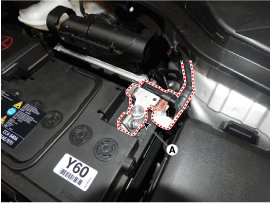
Disconnect the battery (-) terminal (A).
|
| 3. |
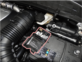
Disconnect the battery positive (+) terminal (A).
|
| 4. |
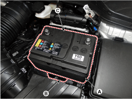
Remove the battery bracket (B).
|
| 5. |
Remove the battery insulation pad (A) and then remove the battery (C).
|
Battery Tray
| 1. |
Remove the battery.
(Refer to "Removal")
|
| 2. |
Remove the ECM.
(Refer to Engine Control / Fuel System - "Engine Control Module (ECM)")
|
| 3. |
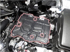
Remove the battery tray (A) after loosening the bolts.
|
| Installation |
| 1. |
Install in the reverse order of removal.
|
| Inspection |
Vehicle parasitic current inspection
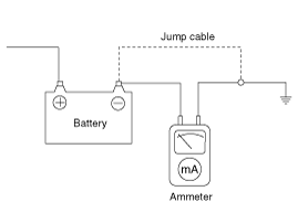
[Using the Ammeter]
| 1. |
Turn the all electric devices OFF, and then turn the ignition switch
OFF.
|
| 2. |
Close all doors except the engine hood, and then lock all doors.
|
| 3. |
Wait a few minutes until the vehicle’s electrical systems go to sleep
mode.
|
| 4. |
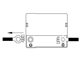
Connect an ammeter in series between the battery (-) terminal and the
ground cable, and then disconnect the clamp from the battery (-) terminal
slowly.
|
| 5. |
Read the current value of the ammeter.
|
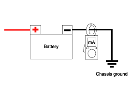
[Using the Clamp type Ammeter]
| 6. |
Turn the all electric devices OFF, and then turn the ignition switch
OFF.
|
| 7. |
Close all doors except the engine hood, and then lock all doors.
|
| 8. |
Wait a few minutes until the vehicle’s electrical systems go to sleep
mode.
|
| 9. |
Install the clamp type ammerter on battery negative (-) terminal.
|
| 10. |
Read the current value of the ammeter.
|
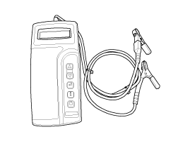
The Micro 570 Analyzer
The Micro 570 Analyzer provides the ability to test the charging and starting
systems, including the battery, starter and alternator.
※ Because of the possibility of personal injury, always use extreme
caution and appropriate eye protection when working with batteries.
※ When charging battery by test result, Battery must be fully charged.
|
Keypad
The Micro 570 button on the key pad provide the following functions :
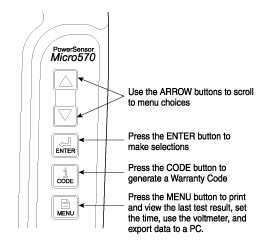
Battery Test Procedure
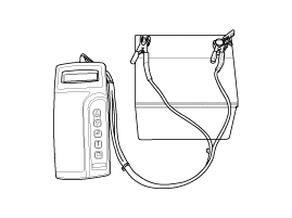
| 1. |
Connect the tester to the battery.
|
| 2. |
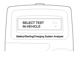
The tester will ask if the battery is connected "IN-VEHICLE" or "OUT-OF-VEHICLE".
Make your selection by pressing the arrow buttons; then press ENTER.
|
| 3. |
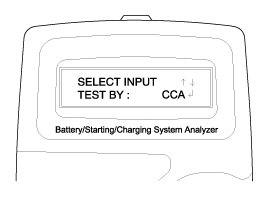
Select CCA and press the ENTER button.
|
| 4. |
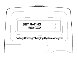
Set the CCA value displayed on the screen to the CCA value marked on
the battery label by pressing up and down buttons and press ENTER.
|
| 5. |
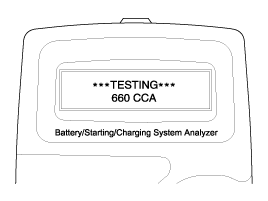
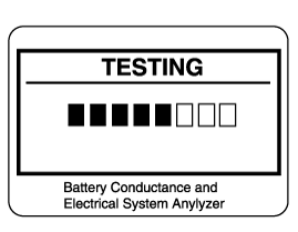
The tester will conduct battery test.
|
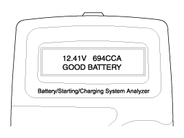
| 6. |
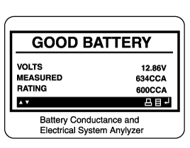
The tester displays battery test results including voltage and battery
ratings.
Refer to the following table and take the appropriate action as recommended
by the Micro 570.
Battery Test Results
[Charge and Retest method after battery charge]
Battery charge
Set battery charger to ‘Auto Mode’ (The Mode that charging current
drops as the battery charges.) and charge battery until charging current
down close to zero or the charger alerts you with an alarm when charge
is complete.
(Minimum charging time recommended : More than 3 hours with Auto Mode
that explained above)
Battery Test after charge
Do not test battery right after the charge. Test battery after battery
surface voltage has subsided as instructed in the following procedure.
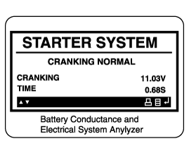
Starter Test Procedure
|
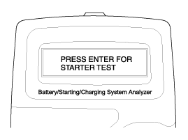
| 7. |
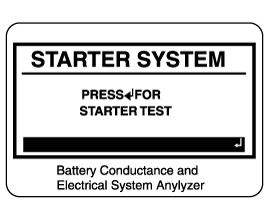
After the battery test, press ENTER immediately for the starter test.
|
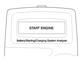
| 8. |
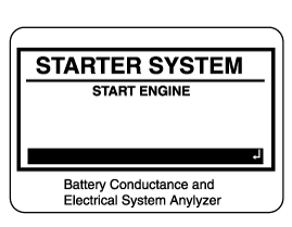
Start the engine.
|
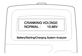
| 9. |
Cranking voltage and starter test results will be displayed on the screen.
Refer to the following table and take the appropriate action as recommended
by the Micro 570.
Starter Test Results
Charging System Test Procedure
|
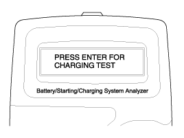
| 10. |
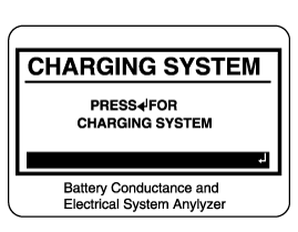
Press ENTER to begin charging system test.
|
| 11. |
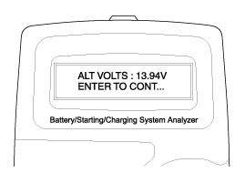
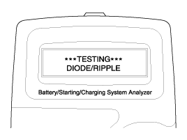
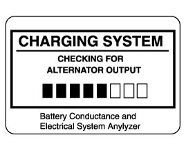
The tester displays the actual voltage of alternator.
Press ENTER to continue.
|
| 12. |
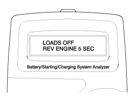
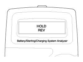
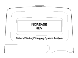
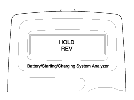
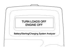
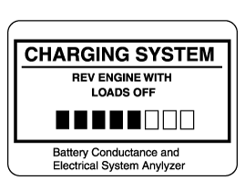
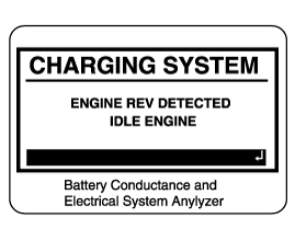
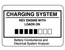
Turn off all electrical load and rev engine for 5 seconds with pressing
the accelerator pedal. (Follow the instructions on the screen)
|
| 13. |
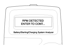
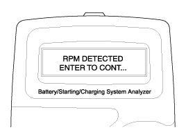
The message that engine RPM is detected will be displayed on the screen.
Press ENTER to continue.
|
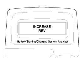
| 14. |
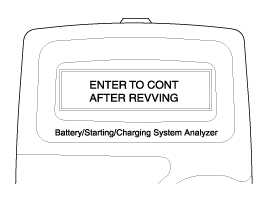
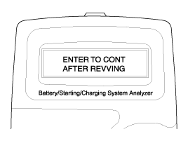
If the engine RPM is not detected, press ENTER after revving engine.
|
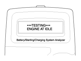
| 15. |
The tester will conduct charging system test during loads off.
|
| 16. |
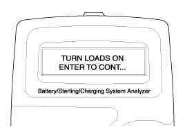
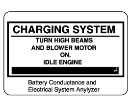
Turn on electrical loads (air conditioner, lamps, audio and etc). Press
ENTER to continue.
|
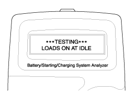
| 17. |
The tester will conduct charging system test during loads on.
|
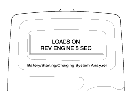
| 18. |
Rev engine for 5 seconds with pressing the accelerator pedal. (Follow
the instructions on the screen)
|
| 19. |
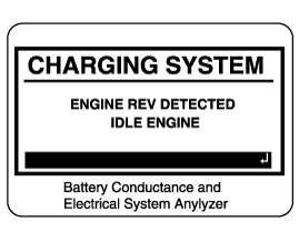
The message that engine RPM is detected will be displayed on the screen.
Press ENTER to continue.
|
| 20. |
If the engine RPM is not detected, press ENTER after revving engine.
|
| 21. |
Turn off electrical loads (air conditioner, lamps, audio and etc). Turn
the engine off.
|
| 22. |
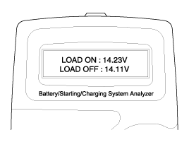
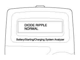
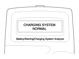
Charging voltage and charging system test results will be displayed
on the screen.
Shut off engine end disconnect the tester clamps from the battery. Refer
to the following table and take the appropriate action as recommended
by the Micro 570.
Charging System Test Results
|
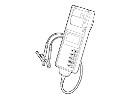
The MDX-670P Analyzer
The MDX-670P battery conductance and electrical system analyzer tests batteries
as well as starting and charging systems for vehicle.
It displays the test results in seconds and features a built-in printer to provide
a copy of the results.
|
|
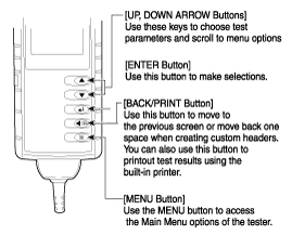
| 1. |
Connect the red clamp to the positive (+) terminal and the black clamp
to the negative (-) terminal.
|
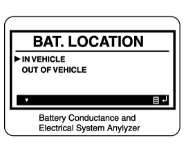
| 2. |
Scroll to and select IN VEHICLE or OUT OF VEHICLE for a battery not
connected to a vehicle.
|
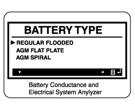
| 3. |
Scroll to and select REGULAR FLOODED, AGM FLAT PLATE, or AGM SPIRAL
where applicable.
|
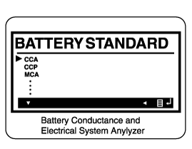
| 4. |
Scroll to and select the battery’s rating system.
|
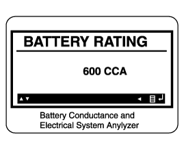
| 5. |
Set the selected rating value displayed on the screen to the value marked
on the battery label by pressing up and down arrow buttons.
|
| 6. |
Press ENTER to start test.
|
| 7. |
After several seconds the tester displays the decision on the battery’s
condition and the measured voltage. The tester also displays your selected
battery rating and the rating units.
Battery Test Results
[Charge and Retest method after battery charge]
Battery charge
Set battery charger to 'Auto Mode' (The Mode that charging current drops
as the battery charges.) and charge battery until charging current down
close to zero or the charger alerts you with an alarm when charge is
complete. (Minimum charging time recommended : More than 3 hours with
Auto Mode that explained above)
Battery Test after charge
Do not test battery right after the charge. Test battery after battery
surface voltage has subsided as instructed in the following procedure.
|
| 8. |
Press the ENTER button to proceed with the starter test.
|
| 9. |
Start the engine when prompted.
|
| 10. |
The tester displays the decision on the starter system, cranking voltage,
and cranking time in milliseconds.
Starter Test Results
Step 3 : Charging System Test
|
| 11. |
Press the ENTER button to proceed with the charging test.
|
| 12. |
Rev the engine with loads off. (Following the on-screen prompts)
|
| 13. |
The message that engine RPM is detected will be displayed on the screen,
idle the engine.
|
| 14. |
Turn on electrical loads (air conditioner, lamps, audio and etc). Press
ENTER to continue.
|
| 15. |
Turn on electrical loads (air conditioner, lamps, audio and etc). Press
ENTER to continue.
|
| 16. |
The message that engine RPM is detected will be displayed on the screen,
idle the engine.
|
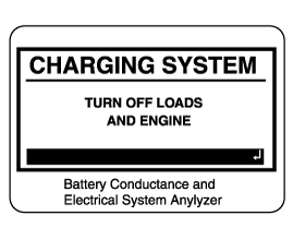
| 17. |
Turn off loads and engine.
|
| 18. |
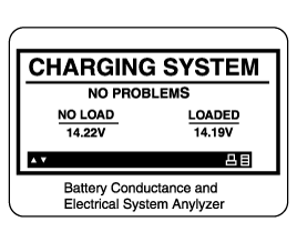
The Charging System decision is displayed at the end of the procedure.
|
| 19. |
Press the BACK/PRINT button to print the test results or MENU to return
to the Options Menu.
|
| Cleaning |
| 1. |
Make sure the ignition switch and all accessories are in the OFF position.
|
| 2. |
Disconnect the battery cables (negative first).
|
| 3. |
Remove the battery from the vehicle.
|
| 4. |
Inspect the battery tray for damage caused by the loss of electrolyte.
If acid damage is present, it will be necessary to clean the area with
a solution of clean warm water and baking soda. Scrub the area with
a stiff brush and wipe off with a cloth moistened with baking soda and
water.
|
| 5. |
Clean the top of the battery with the same solution as described above.
|
| 6. |
Inspect the battery case and cover for cracks. If cracks are present,
the battery must be replaced.
|
| 7. |
Clean the battery posts with a suitable battery post tool.
|
| 8. |
Clean the inside surface of the terminal clamps with a suitable battery
cleaning tool. Replace damaged or frayed cables and broken terminal
clamps.
|
| 9. |
Install the battery in the vehicle.
|
| 10. |
Connect the cable terminals to the battery post, making sure tops of
the terminals are flush with the tops of the posts .
|
| 11. |
Tighten the terminal nuts securely.
|
| 12. |
Coat all connections with light mineral grease after tightening.
|
 Battery Description and operation
Description
1.
The CMF (Closed Maintenance Free) battery is, as the name implies, totally
maintenance free and has no removable battery cell caps.
...
 Battery Troubleshooting
Troubleshooting
...
Other information:
Hyundai Kona (OS) 2018-2026 Service Manual: Rear Bumper beam Assembly Components and components location
Component Location
1. Rear bumper beam assembly
...
Hyundai Kona (OS) 2018-2026 Service Manual: Troubleshooting
Troubleshooting
Symptom
Suspect Area
Remedy
Engine will not start or is hard to
start (Cranks OK)
Ignition lock switch
Inspect ignition lock switch, or replace as required
Ignition coil
...
© 2018-2026 www.hkona.com

