Hyundai Kona: Engine and Transaxle Assembly / Engine and Transaxle Assembly Repair procedures
| • |
Use fender covers to avoid damaging painted surfaces.
|
| • |
To avoid damage, unplug the wiring connectors carefully while
holding the connector portion.
|
|
| • |
Mark all wiring and hoses to avoid misconnection.
|
| • |
To release the fuel system pressure before removing the engine
assembly, start the engine with the fuel pump relay removed.
And then turn off the ignition switch after engine stops.
|
|
| 1. |
Disconnect the battery negative terminal.
|
| 2. |
Remove the engine cover.
(Refer to Engine and Transaxle Assembly - "Engine Cover")
|
| 3. |
Remove the air duct and air cleaner assembly.
(Refer to Intake and Exhaust System - "Air Cleaner")
|
| 4. |
Remove the battery.
(Refer to Engine Electrical System - "Battery")
|
| 5. |
Remove the engine control module (ECM).
(Refer to Engine Control/Fuel System - "Engine Control Module (ECM)")
|
| 6. |
Remove the battery tray.
(Refer to Engine Electrical System - "Battery")
|
| 7. |
Remove the engine room under cover.
(Refer to Engine and Transaxle Assembly - "Engine Room Under Cover")
|
| 8. |
Loosen the drain plug and drain the coolant and remove the radiator
cap to speed draining.
(Refer to Cooling System - "Coolant")
|
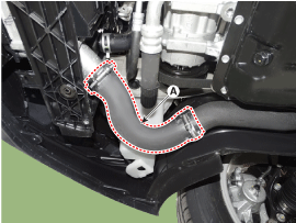
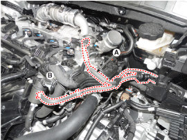
| 9. |
Remove the intercooler inlet hose (A).
|
Tightening torque :
4.9 - 6.9 N.m (0.5 - 0.7 kgf.m, 3.6 - 5.1 lb-ft)
|
| •
|
It is allowed to plaster cleaning liquid or alcohol
on the connecting surfaces of hose and pipe, but all
kinds of oil is prohibited.
|
| •
|
The groove of hose must be in line with the protrusion
of the pipe.
|
| •
|
The band must be located on the position mark of hose
and must not run over it.
|
| •
|
Tighten the torque control cap until it separated. If
a torque control cap has already removed, tighten the
screw at the specified torque.
|
|
|
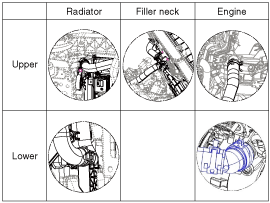
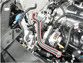
| 10. |
Disconnect the radiator upper hose (A).
| •
|
When installing radiator hoses, install as shown in
illustrations.
|
|
|
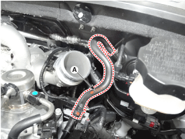
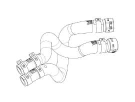
| 11. |
Disconnect the radiator lower hose (A).
| •
|
When installing radiator hoses, install as shown in
illustrations.
|
|
|
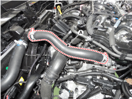
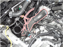
| 12. |
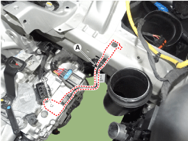
Remove the intercooler outlet hose and pipe.
| (1) |
Disconnect the intercooler outlet hose (A).
|
| (2) |
Disconnect the boost pressure sensor (BPS) connector (B).
|
| (3) |
Disconnect the RCV solenoid hose (C).
|
| (4) |
Disconnect the RCV solenoid connector (D).
|
Tightening torque :
4.9 - 6.9 N.m (0.5 - 0.7 kgf.m, 3.6 - 5.1 lb-ft)
|
|
• |
It is allowed to plaster cleaning liquid or
alcohol on the connecting surfaces of hose and
pipe, but all kinds of oil is prohibited.
|
|
• |
The marking of hose must be in line with the
stopper of the throttle body.
|
|
• |
The band must be located on the position mark
of hose and must not run over it.
|
|
• |
Tighten the torque control cap until it separated.
If a torque control cap has already removed,
tighten the screw at the specified torque.
|
|
|
|
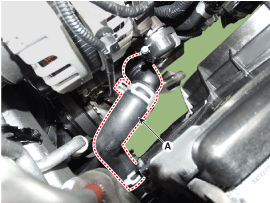
| 13. |
Disconnect the fuel hose (A) and the purge control solenoid valve (PCSV)
hose (B).
|
| 14. |
Disconnect the reservoir tank water hose (A).
|
| 15. |
Disconnect the brake booster vacuum hose (A).
|
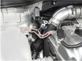
| 16. |
Disconnect the heater hoses (A).
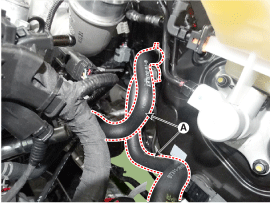
| •
|
When installing heater hoses, install as shown in illustrations.
|
|
|
| 17. |
Disconnect the wiring harness from the engine room.
| (1) |
Remove the ground bolt (A)
|
| (2) |
Disconnect the battery negative terminal connector (B)
|
| (3) |
Disconnect the front harness connector (C)
|
| (4) |
Disconnect the PCB block (D)
|
| (5) |
Disconnect the wiring protector (E)
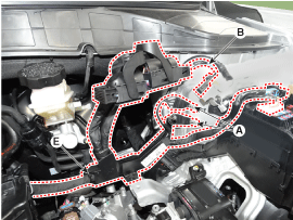
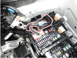
|
| (6) |
Disconnect the battery positive wirings (A)
|
| (7) |
Disconnect the wiring protector (B)
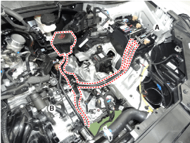
|
|
| 18. |
Recover the refrigerant and then remove the high pressure pipe and low
pressure pipe.
(Refer to Heating, Ventilation Air conditioning - "Compressor")
|
| 19. |
Remove the transaxle wire harness connectors and control cable from
the transaxle.
(Refer to Dual Clutch Transmission (DCT) System - "Dual Clutch Control
System")
|
| 20. |
Remove the front muffler.
(Refer to Intake and Exhaust System - "Muffler")
|
| 21. |
Remove the steering U-joint mounting bolt.
(Refer to Steering System - "Steering Column and Shaft")
|
| 22. |
Remove the roll rod bracket (A).
|
Tightening torque
Bolt (B) :
107.9 - 127.5 N.m (11.0 - 13.0 kgf.m, 79.6 - 94.0 lb-ft)
Bolts (C) :
49.0 - 63.7 N.m (5.0 - 6.5 kgf.m, 36.2 - 47.0 lb-ft)
|
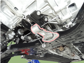
|
| 23. |
Remove the roll rod mounting support bracket (A).
|
Tightening torque :
49.0 - 68.6 N.m (5.0 - 7.0 kgf.m, 36.2 - 50.6 lb-ft)
|
|
| 24. |
Remove the sub frame.
(Refer to Suspension System - "Sub Frame")
|
| 25. |
Support the sub frame with a floor jack.
|
| 26. |
Disconnect the engine ground cable (A).
|
Tightening torque :
10.8 - 13.7 N.m (1.1 - 1.4 kgf.m, 8.0 - 10.1 lb-ft)
|
|
| 27. |
Disconnect the transaxle ground cable (A).
|
Tightening torque :
10.8 - 13.7 N.m (1.1 - 1.4 kgf.m, 8.0 - 10.1 lb-ft)
|
|
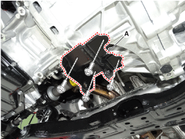
| 28. |
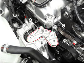
Remove the engine mounting support bracket (A).
|
Tightening torque
Nut (B) :
78.5 - 98.1 N.m (8.0 - 10.0 kgf.m, 57.9 - 72.3 lb-ft)
Bolt (C), Nuts (D) :
58.8 - 73.5 N.m (6.0 - 7.5 kgf.m, 43.4 - 54.2 lb-ft)
|
|
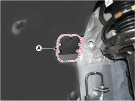
| 29. |
Remove the service cover (A).
|
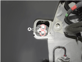
| 30. |
Remove the transaxle support bracket mounting bolts (A).
|
Tightening torque :
107.9 - 127.5 N.m (11.0 - 13.0 kgf.m, 79.6 - 94.0 lb-ft)
|
|
| 31. |
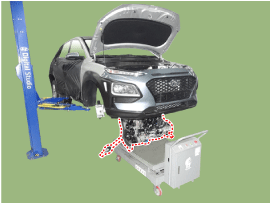
Remove the engine and transaxle assembly by lifting vehicle.
| •
|
Before removing the engine and transaxle assembly, make
sure hoses and wire connectors are disconnected.
|
| •
|
When removing the engine and transaxle assembly, be
careful not to damage any surrounding parts or body
components.
|
|
|
Installation is in the reverse order of removal.
Perform the following :
| • |
Adjust a shift cable.
|
| • |
Refill engine with engine oil.
|
| • |
Refill a transaxle with fluid.
|
| • |
Refill a radiator and a reservoir tank with engine coolant.
|
| • |
Inspect for fuel leakage.
|
| – |
After assemble the fuel line, turn on the ignition switch (do not operate
the starter) so that the fuel pump runs for approximately two seconds
and fuel line pressurizes.
|
| – |
Repeat this operation two or three times, then check for fuel leakage
at any point in the fuel line.
|
| • |
Place a heater control knob on "HOT" position.
|
| • |
Bleed air from the cooling system.
|
| – |
Start engine and let it run until it warms up. (until the radiator fan
operates 3 or 4 times.)
|
| – |
Turn off the engine. Check the level in the radiator, add coolant if
needed. This will allow trapped air to be removed from the cooling system.
|
| • |
Clean battery posts and cable terminals and assemble.
|
Removal and Installation
Roll rod bracket
1.
Remove the engine room under cover.
(Refer to Engine and Transaxle Assembly - "Engine Room Under Cover&qu ...


 Engine Mounting Repair procedures
 Timing System