Hyundai Kona: ABS (Anti-Lock Brake System) / Schematic diagrams
Hyundai Kona (OS) 2018-2026 Service Manual / Brake System / ABS (Anti-Lock Brake System) / Schematic diagrams
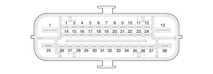
| Schematic Diagrams |
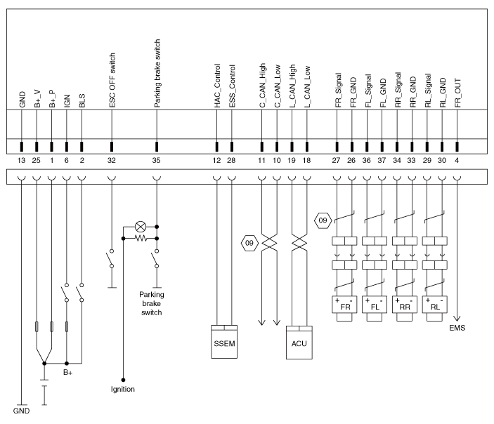
| Termianal function |
|
Pin No |
Description |
Current 12V / 20C (AMP) |
Voltage range (V) |
|
1 |
Voltage supply for pump motor |
≤ 34 |
0 - 18 |
|
2 |
Brake light switch |
≤ 22m |
0 - 18 |
|
4 |
FR Wheel speed sensor power |
- |
0 - 18 |
|
6 |
IGN 1 |
≤ 10m |
0 - 18 |
|
10 |
C-CAN low |
44m typ. |
0 - 18 |
|
11 |
C-CAN high |
44m typ. |
0 - 18 |
|
12 |
HAC control |
- |
0 - 18 |
|
13 |
Ground for recirculation pump |
- |
- |
|
18 |
L-CAN low |
44m typ. |
0 - 18 |
|
19 |
L-CAN high |
44m typ. |
0 - 18 |
|
25 |
Voltage supply for solenoid valves |
≤ 17 |
0 - 18 |
|
26 |
FR Wheel speed sensor ground |
≤ 34m |
0 - 18 |
|
27 |
FR Wheel speed sensor signal |
≤ 34m |
0 - 18 |
|
28 |
ESS control |
- |
0 - 18 |
|
29 |
RL Wheel speed sensor signal |
≤ 34m |
0 - 18 |
|
30 |
RL Wheel speed sensor ground |
≤ 34m |
0 - 18 |
|
32 |
VDC switch |
≤ 18m |
0 - 18 |
|
33 |
RR Wheel speed sensor signal |
≤ 34m |
0 - 18 |
|
34 |
RR Wheel speed sensor ground |
≤ 34m |
0 - 18 |
|
35 |
Parking brake switch |
≤ 18m |
0 - 18 |
|
36 |
FL Wheel speed sensor signal |
≤ 34m |
0 - 18 |
|
37 |
FL Wheel speed sensor ground |
≤ 34m |
0 - 18 |
 Description and operation
Description
This specification applies to HCU (Hydraulic Control Unit) and ECU (Electronic
Control Unit) of the HECU (Hydraulic and Electronic Control Unit).
This specification ...
 Repair procedures
Inspection
ABS System Bleeding
This procedure should be followed to ensure adequate bleeding of air and filling
of the ESC unit, brake lines and master cylinder with brake fluid ...
Other information:
Hyundai Kona (OS) 2018-2026 Service Manual: Components and components location
Component Location
1. Power door mirror
2. Power door mirror switch
3. Power folding mirror switch
...
Hyundai Kona (OS) 2018-2026 Service Manual: Gear Actuator Assembly Description and operation
Description
•
Components location : DCT (Dual Clutch Transmission)
•
Function
The gear actuator comprises the shift motor and select solenoid.
Gear actuator shift motor and select solenoid receive signals fro ...
© 2018-2026 www.hkona.com
