
Hyundai Kona: Seat Electrical / Air Ventilation Seat Schematic diagrams
Hyundai Kona (OS) 2018-2026 Service Manual / Body Electrical System / Seat Electrical / Air Ventilation Seat Schematic diagrams
| Circuit Diagram |
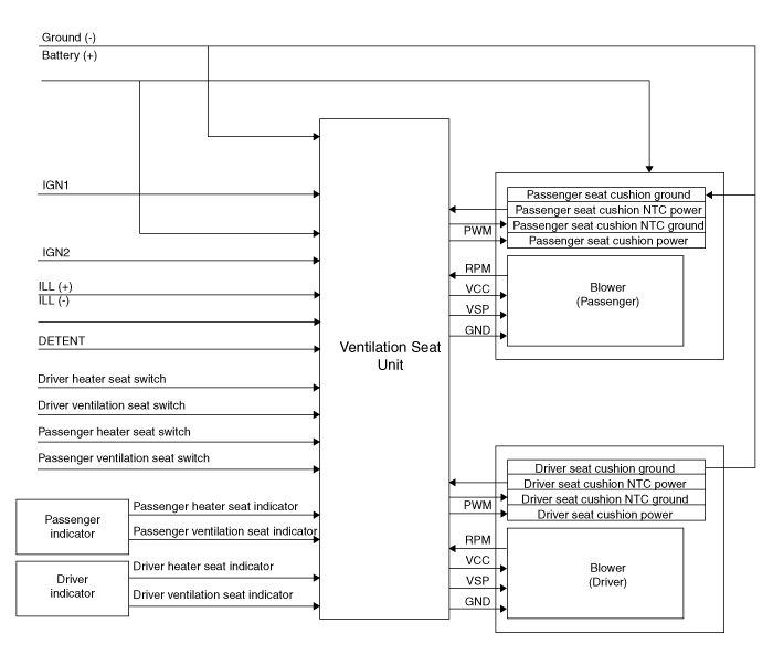
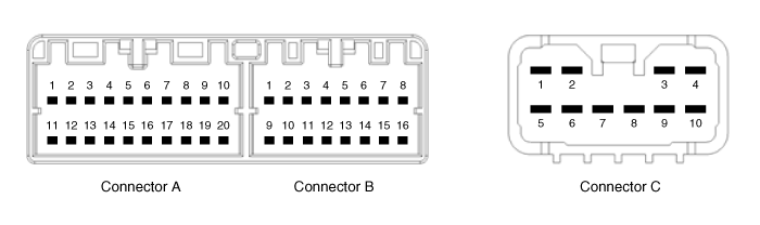
|
N |
Connector A |
Connector B |
Connector C |
|
1 |
Ventilation seat unit IGN1 |
Driver ventilation indicator(low) |
Ventilation heater power |
|
2 |
Driver blower power |
Driver ventilation indicator(mid) |
Driver heater power |
|
3 |
Driver blower speed |
Driver ventilation indicator(high) |
Driver heater ground |
|
4 |
Driver RPM input |
Dirver NTC (+) |
Ventilation heater groung |
|
5 |
Driver heater switch |
- |
Ventilation heater power |
|
6 |
Driver ventilation switch |
ILL (-) |
- |
|
7 |
ILL (+) |
Driver NTC (-) |
Passenger heater power |
|
8 |
Driver heater indicator(low) |
Driver blower ground |
- |
|
9 |
Driver heater indicator(mid) |
Passenger ventilation indicator(low) |
Passenger heater ground |
|
10 |
Driver heater indicator(high) |
Passenger ventilation indicator(mid) |
Ventilation heater groung |
|
11 |
Ventilation unit IGN2 |
Passenger ventilation indicator(high) |
|
|
12 |
Passenger blower power |
Passenger NTC (+) |
|
|
13 |
Passenger blower speed |
- |
|
|
14 |
Passenger blower RPM input |
- |
|
|
15 |
Passenger heater switch |
Passenger NTC (-) |
|
|
16 |
Passenger ventilation switch |
Passenger blower ground |
|
|
17 |
Detent |
|
|
|
18 |
Passenger heater indicator(low) |
||
|
19 |
Passenger heater indicator(mid) |
||
|
20 |
Passenger heater indicator(high) |
 Air Ventilation Seat Components and components location
Component Location
[Front Ventilation Seat]
1. Ventilation seat unit
(Assist seat only)
2. Ventilation seat blower
...
 Air Ventilation Seat Repair procedures
Removal
[Ventilation Blower]
1.
Disconnect the negative (-) battery terminal.
2.
Remove the front seat.
...
Other information:
Hyundai Kona (OS) 2018-2026 Service Manual: Rear Center Seat Belt Retractor Components and components location
Component Location
1. Rear center seat belt retractor
...
Hyundai Kona (OS) 2018-2026 Owners Manual: Tailgate unlocking
To unlock:
1. Carry the smart key.
2. Either press the tailgate handle button or press the Tailgate Unlock button
(3) on the smart key for more than one second.
3. The hazard warning lights will blink two times.
Information
The Tailgate Unlock button (3) will only unlock the tailgate. It will
n ...
В© 2018-2026 www.hkona.com
