
Hyundai Kona: Cooling System / Coolant Repair procedures
Hyundai Kona (OS) 2018-2026 Service Manual / Engine Mechanical System / Cooling System / Coolant Repair procedures
| Replacement and Air Bleeding |
|

|

| 1. |
Make sure the engine and radiator are cool to the touch.
|
| 2. |
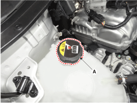
Remove the reservoir tank cap (A).
|
| 3. |
Remove the under cover.
(Refer to Engine and Transaxle Assembly - "Engine room under cover")
|
| 4. |
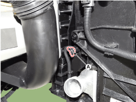
Loosen the drain plug (A), and drain the coolant.
|
| 5. |
Tighten the radiator drain plug securely.
|
| 6. |
After draining engine coolant in the reservoir tank, clean the tank.
|
Filling and Air Bleeding
| 1. |
Fill the radiator with water through the radiator cap and tighten the
cap.
|

| 2. |
Start the engine and allow to come to normal operating temperature.
Wait for the cooling fans to turn on several times. Accelerate the engine
to aid in purging trapped air. Shut engine off.
|
| 3. |
Wait until the engine is cool.
|
| 4. |
Repeat steps 1 to 3 until the drained water runs clear.
|
| 5. |
Fill fluid mixture with coolant and water (55-60%) (except for North
America, Europe and China : 45-50%) slowly through the radiator cap.
Push the upper/lower hoses of the radiator so as bleed air easily.
|
| 6. |
Start the engine and run until coolant circulates.
When the cooling fan operates and coolant circulates, refill coolant
through the radiator cap.
|
| 7. |
Repeat step.5 until the cooling fan 3-5 times and bleed air sufficiently
out of the cooling system.
|
| 8. |
Install the radiator cap and fill the reservoir tank to the "MAX" (or
"F") line with coolant.
|
| 9. |
Run the vehicle under idle until the cooling fan operates 2-3 times.
|
| 10. |
Stop the engine and wait coolant gets cool.
|
 Cooling System
...
 Cooling Fan Components and components location
Components
1. Cooler fan
2. Fan motor
3. Cooling fan shroud
4. Cooling fan controller (PWM)
...
Other information:
Hyundai Kona (OS) 2018-2026 Owners Manual: Electronic Stability Control (ESC)
The Electronic Stability Control (ESC) system helps to stabilize the vehicle
during cornering maneuvers.
ESC checks where you are steering and where the vehicle is actually going. ESC
applies braking pressure to any one of the vehicle's brakes and intervenes in the
engine management system to as ...
Hyundai Kona (OS) 2018-2026 Service Manual: Crash Pad Side Cover Repair procedures
Replacement
•
Put on gloves to prevent hand injuries.
•
Wh ...
© 2018-2026 www.hkona.com
