Hyundai Kona: Cylinder Block / Cylinder Block Repair procedures
Hyundai Kona (OS) 2018-2026 Service Manual / Engine Mechanical System / Cylinder Block / Cylinder Block Repair procedures
| Disassembly |
|

|

| 1. |
Remove the engine and transaxle assembly from the vehicle.
(Refer to Engine and Transaxle Assembly - "Engine and Transaxle Assembly")
|
| 2. |
Remove the dual clutch transmission.
(Refer to DCT(Dual clutch Transmission) System - "DCT (Dual clutch Transmission)")
|
| 3. |
Remove the external damper flywheel.
(Refer to Cylinder block - "External Damper Flywheel")
|
| 4. |
Remove the rear oil seal.
(Refer to Cylinder block - "Rear Oil Seal")
|
| 5. |
Install the engine to engine stand for disassembly.
|
| 6. |
Remove the intake manifold.
(Refer to Intake and Exhaust System - "Intake Manifold")
|
| 7. |
Remove the Exhaust manifold.
(Refer to Intake and Exhaust System - "Exhaust Manifold")
|
| 8. |
Remove the timing chain.
(Refet to Timing System - "Timing Chain")
|
| 9. |
Remove the cylinder head Assembly.
(Refet to Cylindet Head Assembly - "Cylinder Head")
|
| 10. |
Remove the oil pan and oil screen.
(Refer to Lubrication System - "Oil Pan")
|
| 11. |
Remove the oil cooler.
(Refer to Lubrication System - "Engine Oil")
|
| 12. |
Remove the oil pressure switch.
(Refer to Lubrication System - "Oil Pressure Switch")
|
| 13. |
Remove the water inlet fitting and thermostat.
(Refer to Cooling System - "Thermostat")
|
| 14. |
Remove the crankshaft position sensor.
(Refer to Engine Control/Fuel System - "Crankshaft Position Sensor (CKPS)")
|
| 15. |
Remove the ladder frame.
(Refer to Cylinder Block Assembly - "Piston and Connecting Rod")
|
| 16. |
Check the connecting rod side clearance.
(Refer to Cylinder Block Assembly - "Piston and Connecting Rod")
|
| 17. |
Check the connecting rod bearing cap oil clearance.
(Refer to Cylinder Block Assembly - "Piston and Connecting Rod")
|
| 18. |
Remove the piston and connecting rod assemblies.
(Refer to Cylinder Block Assembly - "Piston and Connecting Rod")
|
| 19. |
Check the main bearing oil clearance.
(Refer to Cylinder Block Assembly - "Crankshaft")
|
| 20. |
Check the crankshaft end play.
(Refer to Cylinder Block Assembly - "Crankshaft")
|
| 21. |
Remove the crankshaft.
(Refer to Cylinder Block Assembly - "Crankshaft")
|
| 22. |
Remove the knock sensor.
(Refer to Engine Control/Fuel System - "Knock Sensor (KS)")
|
| Inspection |
| 1. |
Using a gasket scraper, remove all the gasket material from the top
surface of the cylinder block.
|
| 2. |
Using a soft brush and solvent, thoroughly clean the cylinder block.
|
| 3. |
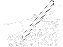
Inspect the top surface of cylinder block for flatness.
Using a precision straight edge and feeler gauge, measure the surface
contacting the cylinder head gasket for warpage.
|
| 4. |
Visually check for scratches on the inside surface of the cylinder bore
and replace the cylinder block if any noticeable scratch is detected.
If deep scratchs are present, replace the cylinder block.
|
| 5. |
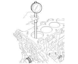
Using the cylinder bore gauge, measure the cylinder bore’s inner diameter
to the axial and axial perpendicular directions.
|
| Reassembly |
| 1. |
Install in the reverse order of disassembly.
|
 Crankshaft Repair procedures
Disassembly
•
Use fender covers to avoid damaging painted surfaces.
...
 Cooling System
...
Other information:
Hyundai Kona (OS) 2018-2026 Service Manual: Sunroof Sunshade Repair procedures
Replacement
1.
Remove the sunroof assembly.
(Refer to Sunroof - "Sunroof Assembly")
2.
After loosening the mounting screws, remove the drip rail assembly (A).
3.
After loosening the m ...
Hyundai Kona (OS) 2018-2026 Owners Manual: Front lamps
Front map lamp (1)
â– Type A (Without sunglass case)
â– Type B (With sunglass case)
Front door lamp () (2) :
The room lamp for the front/rear seats is automatically turned ON for approximately
30 seconds, when a door is opened.
The room lamp for the front/rear seats is automatically turned ON f ...
© 2018-2026 www.hkona.com
