Hyundai Kona: Cylinder Block / Crankshaft Repair procedures
| Disassembly |
|
|
| 1. |
Remove the engine and Transaxle Assembly assembly from the vehicle.
(Refer to Engine and Transaxle Assembly - "Engine and Transaxle Assembly")
|
| 2. |
Remove the dual clutch transmission.
(Refer to Dual clutch Transmission (DCT) System - "Dual clutch Transmission
(DCT)")
|
| 3. |
Remove the external damper flywheel.
(Refer to Cylinder block - "External Damper Flywheel")
|
| 4. |
Remove the rear oil seal.
(Refer to Cylinder block - "Rear Oil Seal")
|
| 5. |
Install the engine to engine stand for disassembly.
|
| 6. |
Remove the intake manifold.
(Refer to Intake and Exhaust System - "Intake Manifold")
|
| 7. |
Remove the exhaust manifold.
(Refer to Intake and Exhaust System - "Exhaust Manifold")
|
| 8. |
Remove the timing chain.
(Refet to Timing System - "Timing Chain")
|
| 9. |
Remove the cylinder head Assembly.
(Refet to Cylindet Head Assembly - "Cylinder Head")
|
| 10. |
Remove the oil pan and oil screen.
(Refer to Lubrication System - "Oil Pan")
|
| 11. |
Remove the oil cooler.
(Refer to Lubrication System - "Engine Oil")
|
| 12. |
Remove the ladder frame.
(Refer to Cylinder Block - "Piston and Connecting Rod")
|
| 13. |
Remove the piston and connecting rod assembly.
(Refer to Cylinder Block- "Piston and Connecting Rod")
|
| 14. |
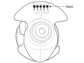
Check the crankshaft main bearing oil clearance.
|
| 15. |
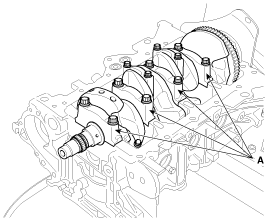
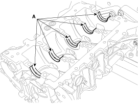
Remove the main bearing caps (A).
|
| 16. |
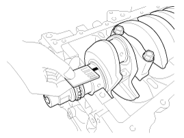
Check the crankshaft end play.
|
| 17. |
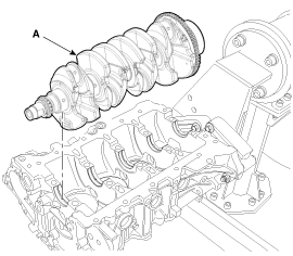
Lift the crankshaft (A) out of the cylinder block, being careful not
to damage journals.
|
| Inspection |
| 1. |
Check the crankshaft main bearing oil clearance.
|
||||||||||||||||||||||||||||||||||||||||||||||||||||||||||||||||||||||||||||||||||||||||||||||||||||
| 2. |
Check the crankshaft end play.
Using a dial indicator, measure the thrust clearance while prying the
crankshaft back and forth with a screwdriver.
|
| Reassembly |
|
| 1. |
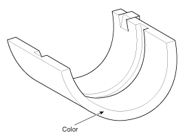
Install the crankshaft main bearings.
|
| 2. |
Install the thrust bearing.
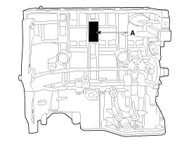
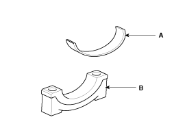
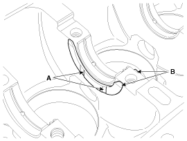
Install the thrust bearing (A) on the No.3 journal position of the cylinder
block with the oil grooves facing outward.
|
| 3. |
Place the crankshaft on the cylinder block.
|
| 4. |
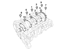
Install the main bearing caps and tighten the cap bolts.
|
| 5. |
Check the crankshaft end play.
|
| 6. |
Install the piston and connecting rod assemblies.
(Refer to Cylinder Block - "Piston and Connecting Rod")
|
| 7. |
Install the ladder frame.
(Refer to Cylinder Block - "Ladder Frame")
|
| 8. |
Install the other parts in the reverse order of disassembly.
|
 Crankshaft Components and components location
Components
1. Crankshaft
2. Crankshaft upper bearing
3. Crankshaft lower bearing
4. Thrust bearing
5. Main bearing cap
6. Crankshaft sproket
7. ...
 Cylinder Block Repair procedures
Disassembly
•
Use fender covers to avoid damaging painted surfaces.
...
Other information:
Hyundai Kona (OS) 2018-2026 Service Manual: Thermostat Repair procedures
Removal
•
Disassembly of the thermostat would have an adverse effect,
causing a lowering of cooling efficiency.
1.
Drain engine coolan ...
Hyundai Kona (OS) 2018-2026 Owners Manual: Winter Precautions
Use high quality ethylene glycol coolant
Your vehicle is delivered with high quality ethylene glycol coolant in the cooling
system. It is the only type of coolant that should be used because it helps prevent
corrosion in the cooling system, lubricates the water pump and prevents freezing.
Be sure ...


