Hyundai Kona: Smart Key System / Smart Key Unit Repair procedures
| Removal |
| 1. |
Disconnect the negative (-) battery terminal.
|
| 2. |
Remove the glove box.
(Refer to Body - "Glove Box Upper Cover Assembly")
|
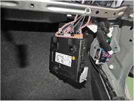
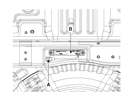
| 3. |
Remove the smart key unit (A), after loosening the bolt and nut.
|
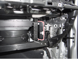
| 4. |
Disconnect the smart key unit connector (B).
|
|

| 1. |
Disconnect the negative (-) battery terminal.
|
| 2. |
Remove the console upper cover.
(Refer to Body - "Floor Console Assembly")
|
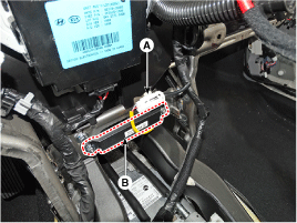
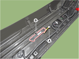
| 3. |
Remove the interior 1 antenna (B) after loosening the mounting nuts
and disconnect the connector (A).
|
| 1. |
Disconnect the negative (-) battery terminal.
|
| 2. |
Remove the console upper cover
(Refer to Body - "Floor Console Assembly")
|
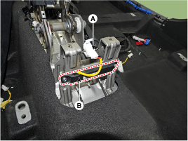
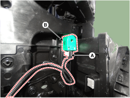
| 3. |
Remove the interior 2 antenna (B) after loosening the mounting nuts
(2EA) and disconnecting the connector (A).
|
| 1. |
Disconnect the negative (-) battery terminal
|
| 2. |
Remove the rear transverse trim.
(Refer to Body - "Trunk Trim")
|
| 3. |
Remove the trunk antenna (B) after disconnect the connector (A)
and loosening the mounting nuts.
|
| 1. |
Disconnect the negative (-) battery terminal.
|
| 2. |
Remove the rear bumper cover.
(Refer to Body - "Rear Bumper Cover")
|
| 3. |
Remove the rear bumper antenna (A) after disconnect the connector
(B) and loosening the mounting nuts.
|
| 1. |
Disconnect the negative (-) battery terminal.
|
| 2. |
Remove the front left wheel guide.
(Refer to Body - "Front Wheel Guard")
|
| 3. |
Remove the buzzer (B) after disconnect the connector (A)
|
| 1. |
Disconnect the negative (-) battery terminal.
|
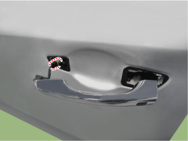
| 2. |
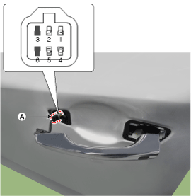
Remove the front outside door handle.
(Refer to Body - "Front Door Outside Handle")
|
| Inspection |
| 1. |
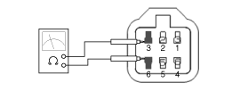
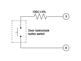
Disconnect the front door outside handle connector (A).
|
| 2. |
Check for continuity between terminals No 3 and No 6.
|
| Installation |
| 1. |
Install the smart key unit.
|
| 2. |
Install the smart key unit mounting bolts and connect the connector.
|
| 3. |
Install the glove box.
|
| 4. |
Install the negative (-) battery terminal and check the smart key
system.
|
| 1. |
Install the interior 1 antenna.
|
| 2. |
Install the crash pad center panel.
|
| 3. |
Install the negative (-) battery terminal and check the smart key
system.
|
| 1. |
Install the interior 2 antenna.
|
| 2. |
Install the console rear complete assembly.
|
| 3. |
Install the negative (-) battery terminal and check the smart key
system.
|
| 1. |
Trunk mounted antenna.
|
| 2. |
Install the rear transverse trim.
|
| 3. |
Install the negative (-) battery terminal and check the smart key
system.
|
| 1. |
Install the rear bumper antenna.
|
| 2. |
Install the rear bumper cover.
|
| 3. |
Install the negative (-) battery terminal and check the smart key
system
|
| 1. |
Install the outside handle.
|
| 2. |
Install the front outside door handle.
|
| 3. |
Install the negative (-) battery terminal and check the smart key
system.
|
 Smart Key Unit Schematic diagrams
Circuit Diagram
...
 Smart Key Diagnostic Repair procedures
Inspection
Self Diagnosis with Scan Tool
It will be able to diagnose defects of SMART KEY system with GDS quickly.
GDS can operates actuator forcefully, input/output va ...
Other information:
Hyundai Kona (OS) 2018-2026 Service Manual: Accelerator Pedal Repair procedures
Removal
1.
Turn the ignition switch OFF and disconnect the negative (-) battery
cable.
2.
Disconnect the accelerator position sensor connector (A).
3.
Remove the installation nuts (A) and then re ...
Hyundai Kona (OS) 2018-2026 Owners Manual: Wipers and washers
A :Wiper speed control (front)
┬╖ / MIST тАУ Single wipe ┬╖ O / OFF
тАУ Off ┬╖ --- / INT тАУ Intermittent wipe AUTO* тАУ Auto control wipe ┬╖ 1 / LOтАУ
Low wiper speed ┬╖ 2 / HI тАУ High wiper speed
B : Intermittent control wipe time adjustment
C :Wash with brief wipes (front)
D : Rear wiper con ...
