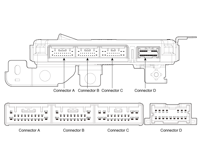
Hyundai Kona: BCM (Body Control Module) / Components and components location
Hyundai Kona (OS) 2018-2026 Service Manual / Body Electrical System / BCM (Body Control Module) / Components and components location
| Components |

|
NO |
Connector A |
Connector B |
Connector C |
Connector D |
|
1 |
Batt (+) |
Front wiper switch |
P CAN (low) |
- |
|
2 |
IGN 1 |
Rear wiper switch |
P CAN (high) |
PAS Switch indicator |
|
3 |
IGN 2 |
Front wiper int vol switch |
PDW buzzer |
Heated steering indicator |
|
4 |
Key in switch |
Fog lamp switch |
Front wiper low relay |
- (Low-side_LED) |
|
5 |
Front wiper switch (Low) |
Auto light power |
- (Low-side) |
- (UIP) |
|
6 |
Rear wiper switch |
NTS sensor |
- (Low-side) |
Wiper relay (High) |
|
7 |
- (Active '- H) |
- (Active '- L, Wake - up)) |
Front wiper hihg relay |
Key solenoid |
|
8 |
Wiper parking switch |
B CAN(low) |
FPAS power |
Rear seat belt indicator(RH) |
|
9 |
- (Active '- H) |
B CAN(high) |
FPAS power |
Rear seat belt indicator(Center) |
|
10 |
- (Active '- H) |
Passenger seat belt |
PAS power |
Rear seat belt indicator(LH) |
|
11 |
- (Active '- L, Wake - up)) |
- (Active '- L, Wake - up)) |
Heated steering power |
ATM solenoid |
|
12 |
ACC |
- (Active '- N, Wake - up)) |
GND |
PAS (LIN) |
|
13 |
Front washer switch |
- (Active '- N, Wake - up)) |
Rear wiper relay |
Rain sensor (LIN) |
|
14 |
Brake switch |
Light switch |
Rear infolding relay |
Wiper relay (Low) |
|
15 |
- (Active '- L, Wake - up)) |
Head lamp switch |
- (Low-side) |
- (Safety power window ECU) |
|
16 |
Steering heater switch |
Auto light powr |
- (Low-side) |
Room lamp |
|
17 |
Sunroof open switch |
Crash signal |
- (Low-side) |
- (Low-side) |
|
18 |
Sunroof open switch |
- |
NTS GND |
|
|
19 |
PAS Input |
Auto light ground |
Multifunction switch GND |
|
|
20 |
Rear defog switch |
Safety power window Enble(high) |
IGN 2 Heated steering power |
|
|
21 |
Key interlock |
|
- |
|
|
22 |
GND |
|
- |
 Specifications
Specifications
Items
Specifications
Rated voltage
DC 12V
Operating voltage
...
 Schematic diagrams
Circuit Diagram
...
Other information:
Hyundai Kona (OS) 2018-2026 Service Manual: Audio Unit Components and components location
Components
[RADIO/MP3]
Connector Pin Information
NO
Connector A
Connector B
Connector C
Connector D
Connector E
1
Rear left speaker (+)
ă…ˇ
GPS sign ...
Hyundai Kona (OS) 2018-2026 Service Manual: Input shaft speed sensor 2 Description and operation
Description
•
Components location : DCT (Dual Clutch Transmission)
•
Function
The input shaft speed sensor is important in that it detects the input
shaft RPM and sends this information to the Transmission Contr ...
© 2018-2026 www.hkona.com
