Hyundai Kona: Indicators And Gauges / Instrument Cluster Repair procedures
| Removal |
|

| 1. |
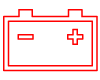
Disconnect the negative (-) battery terminal.
|
| 2. |
Remove the cluster fascia panel.
(Refer to Body - "Cluster Fascia Panel")
|
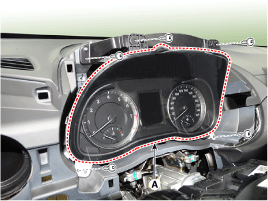
| 3. |
Separate the instrument cluster (A) after loosening the mounting
screws.
|
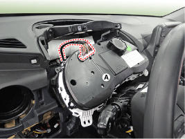
| 4. |
Remover the instrument cluster after disconnect the cluster connector
(A).
|
| Installation |
| 1. |
Install the cluster after connect the cluster connectors.
|
| 2. |
Install the cluster fascia panel.
|
| 3. |
Connect the negative (-) battery terminal.
|

| Inspection |
| 1. |
Check point (Warning indicator)
|


| 2. |
Check point (Gauge)
|
| 1. |
The body electrocal system can be quickly diagnosed failed parts
with vehicle diagnostic system (GDS).
The diagnostic system (GDS) provides the following information.
|
| 2. |
Select the "Car Model" and the system to be checked in order to
check the vehicle with the tester.
|
| 3. |
Select the "Body Control Module (BCM)" to check the "Cluster Module
(CLU)".
|
| 4. |
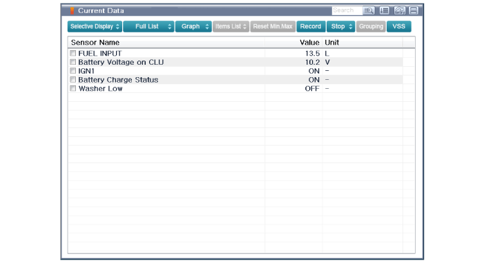
Select the "Current Data" menu to search the current state of the
input/output data.
The input/output data for the sensors corresponding to the cluster
module (CLU) can be checked.
|
| 5. |
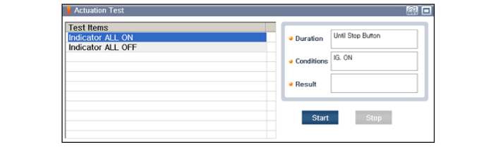
To check the input value of cluster illumination, select option
"Actuation Test".
|
| 1. |
Connect the cable of GDS to the data link connector in driver side
crash pad lower panel, turn the power on GDS.
|
| 2. |
Select model and "BCM".
|
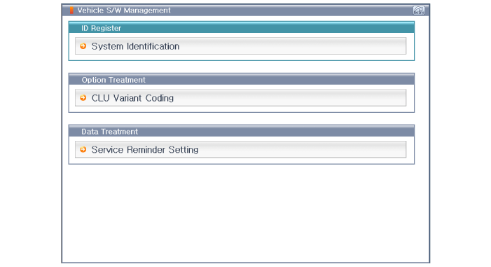
| 3. |
Select Variant coding mode to perform.
|
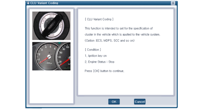
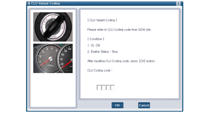
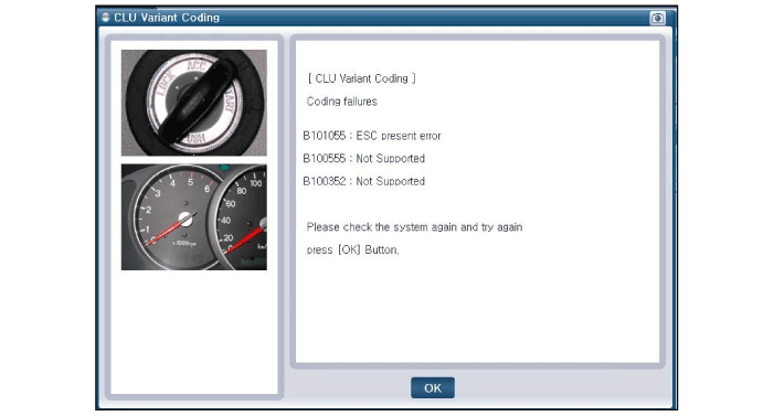
| 4. |
If the trouble codes occurred when performing variant coding, try
the CLU variant coding again after checking the installation status
of CLU system.
|
 Instrument Cluster Description and operation
Description
Communication Network Diagram
Abbreviation
Expalnation
ACU
Airbag Control Unit
...
 Power Door Locks
...
Other information:
Hyundai Kona (OS) 2018-2026 Service Manual: Cylinder Block Repair procedures
Disassembly
•
Use fender covers to avoid damaging painted surfaces.
•
To avoid damaging the cylinder head, wait until the engine coolan ...
Hyundai Kona (OS) 2018-2026 Owners Manual: LED Headlamp Warning Light
This warning light illuminates:
When you turn the ignition switch or the Engine Start/Stop button to the
ON position.
When there is a malfunction with the LED headlamp.
In this case, we recommend that you have the vehicle inspected by an an authorized
HYUNDAI dealer.
This warning light blink ...
