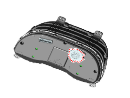
Hyundai Kona: Indicators And Gauges / Instrument Cluster Description and operation
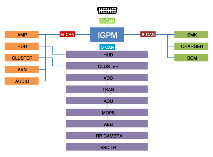
Communication Network Diagram

Abbreviation
|
Expalnation
|
ACU
|
Airbag Control Unit
|
AEB
|
Autonomous Emergency Braking
|
AMP
|
Amplifier
|
AVN
|
Head Unit (Audio / AVN)
|
B_CAN
|
Body Controller Area Network
|
BCM
|
Body Control Module
|
BCW
|
Blind-Spot Collision Warning Indicator
|
C_CAN
|
Chassis Controller Area Network
|
CLU
|
Cluster Module
|
CARMERA
|
Rear View Carmera
|
M_CAN
|
Multi media Controller Area Network
|
MDPS
|
Motor Driven Power Steering
|
P_CAN
|
Powertrain Controller Area Network
|
SJB
|
Smart Junction Block
|
SMK
|
Smart Key Unit
|
Cluster Variant Coding
As we have more options (ESC, MDPS, SCC, etc.) in the car, the dashboard
now have more information to display depending on the chosen options.
For this reason, we need to learn which options the current vehicle when
we replace the dashboard.
To address this issue, a course of learning based on the option required
for the vehicle when replacing the dashboard should be carried out.
This is called Variant Coding.
Function
| 1. |
High speed CAN communication (C-CAN)
| – |
Custom Function : Boarding interlocking sheets, Welcome
Light
|
| – |
LDW : Lane Departure Warning
|
| – |
SPAS: Smart Parking Assist System
|
|
| 2. |
Low speed CAN communication (MM-CAN)
| – |
AV : Audio / Video Multimedia information Display
|
| – |
TBT : Turn By Turn Navigation Information Display
|
|
| 3. |
Sound output
Instrument cluster and the external speakers connected to the output
of the various beeps and sound effects.
If External AMP is applied, the directional alarm is outputted through
the amp.

|
| 4. |
User Setting Mode (USM)
Setting can be changed by using switchs (Menu, UP, Down and OK button).
There are many items (for example, In/Out Seat Synchronization,
In/Out Steering Wheel Synchronization, Auto Door Lock, Auto Door
Lock Deactivate, Head Lamp Escort, Welcome Light, Welcome Sound,
One Touch Turn Signal, Average Fuel Consumption Auto Reset, Brightness,
and Content Setup) that can be set and customized. The signal flow
during setting is as follows.
| (1) |
UMS settings are set, they are transmitted to BCM.
|
| (2) |
BCM transmits the settings via B_CAN to the relevant modules.
|
| (3) |
The module completes setting and transmits the modified
setting to BCM.
|
| (4) |
BCM transmits the final settings via C_CAN to the cluster.
|
• |
The cluster communicates directly with C-CAN
units.
|
|
|
|
Circuit Diagram
[Mono type (3.5")]
[Super vision type (4.2")]
[Super vision type (4.2")]
...
Removal
•
Put on gloves to protect your hands.
...
Other information:
Hyundai Kona (OS) 2018-2026 Owners Manual: Resetting the system
The last break time is set to 00:00 and the driver's attention level is
set to 5 (very attentive) when the driver resets the Driver Attention Warning
(DAW) system.
The Driver Attention Warning (DAW) system resets the last break time to
00:00 and the driver's attention level to 5 in the foll ...
Hyundai Kona (OS) 2018-2026 Owners Manual: Air conditioning refrigerant label
The actual Air Conditioning refrigerant label in the vehicle may differ from
the illustration.
Each symbols and specification on air conditioning refrigerant label means as
below:
1. Classification of refrigerant 2. Amount of refrigerant 3. Classification
of Compressor lubricant
You can find out ...

 Instrument Cluster Schematic diagrams
 Instrument Cluster Repair procedures

