
Hyundai Kona: Timing System / Timing Chain Cover & Oil Pump Assembly Repair procedures
Hyundai Kona (OS) 2018-2026 Service Manual / Engine Mechanical System / Timing System / Timing Chain Cover & Oil Pump Assembly Repair procedures
| Removal |
|

|

|

| 1. |
Disconnect the battery negative terminal.
|
| 2. |
Remove the engine room under cover.
(Refer to Engine and Transaxle Assembly - "Engine Room Under Cover")
|
| 3. |
Remove the passenger side front tire.
(Refer to suspension system - "Wheel")
|
| 4. |
Remove the engine cover.
(Refer to Engine and Transaxle Assembly - "Engine Cover")
|
| 5. |
Remove the drive belt.
(Refer to Timing System - "Drive Belt")
|
| 6. |
Remove the intercooler inlet hose and pipe.
|
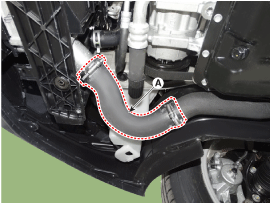
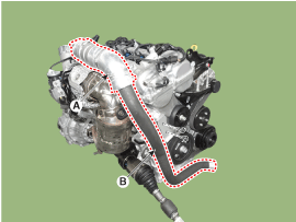
| 7. |
Remove the alternetor.
(Refer to Engine Electrical System - "Alternator")
|
| 8. |
Remove the drive belt tensioner.
(Refer to Timing System - "Drive belt tensioner")
|
| 9. |
Remove the crankshaft damper pulley.
(Refer to Timing System - Crankshaft Damper Pulley")
|
| 10. |
Remove the water pump pulley and water pump.
(Refer to Cooling System - "Water Pump")
|
| 11. |
Remove the idler.
(Refer to Timing System - "Idler")
|
| 12. |
Remove the cylinder head cover.
(Refer to Cylinder Head Assembly - "Cylinder Head Cover")
|
| 13. |
Remove the engine mounting support bracket.
(Refer to Engine and Transaxle Assembly - "Engine Mounting")
|
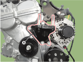
| 14. |
Remove the engine support bracket (A).
|
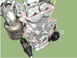
| 15. |
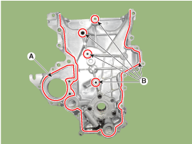
Remove the timing chain cover & oil pump assembly (A).
|
| Installation |
| 1. |
Install the timing chain cover & oil pump assembly.
|

| 2. |
Install in the reverse order of removal.
|
 Timing Chain Cover & Oil Pump Assembly Components and components location
Components
1. Timing chain cover & Oil pump
assembly
...
 Timing Chain Components and components location
Components
1. Timing
chain
2. Timing chain guide
3. Timing
chain arm
4. Timing chain auto tensioner
...
Other information:
Hyundai Kona (OS) 2018-2026 Service Manual: Front Stabilizer Bar Repair procedures
Removal
1.
Loosen the wheel nuts slightly.
Raise the vehicle, and make sure it is securely supported.
2.
Remove the front wheel and tire (A) from the front hub.
Tightening torque :
107.9 - 12 ...
Hyundai Kona (OS) 2018-2026 Service Manual: Radiator Repair procedures
Removal and Installation
1.
Loosen the drain plug, and drain the coolant and remove the radiator
cap to speed draning.
(Refer to Cooling System - "Coolant")
2.
Remove the cooling fan.
(Refer to Cooling Syste ...
© 2018-2026 www.hkona.com
