Hyundai Kona: Brake System / Brake Line Repair procedures
| Removal |
| 1. |
Turn ignition switch OFF and disconnect the battery negative (-) cable.
|
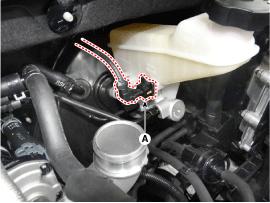
| 2. |
Disconnect the brake fluid level switch connector (A)
|
| 3. |
Remove the brake fluid from the master cylinder reservoir with a syringe.
|

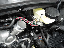
| 4. |
Loosen the flare nuts and then separate the brake tube (A) from the
master cylinder.
|
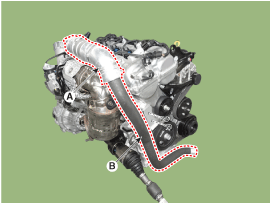
| 5. |
Separate the intercooler inlet hose (A) from the turbocharger and then
remove the inter cooler inlet pipe (B). [Gasoline 1.6 T-GDI]
|
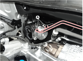
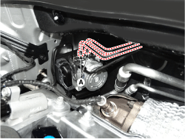
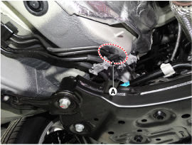
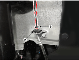
| 6. |
Loosen the flare nuts (A) from the VDC control module (HECU) and remove
the brake tube.
|
| 1. |
Turn ignition switch OFF and disconnect the negative (-) battery cable.
|
| 2. |
Disconnect the brake fluid level switch connector (A).
|
| 3. |
Remove the brake fluid from the master cylinder reservior with a syringe.
|
| 4. |
Separate the intercooler inlet hose (A) from the turbocharger and then
remove the inter cooler inlet pipe (B). [Gasoline 1.6 T-GDI]
|
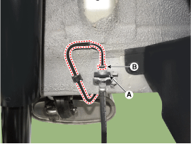
| 5. |
Loosen the flar nuts (A) from the VDC control module (HECU).
|
| 6. |
Remove the air cleaner.
(Refer to Engine Mechanical System - "Air Cleaner")
|
| 7. |
Remove the battery.
(Refer to Engine Electrical System - "Battery")
|
| 8. |
Remove the ECM.
(Refer to Engine Control System - "ECM")
|
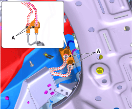
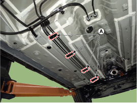
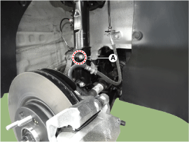
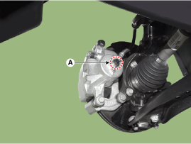
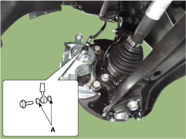
| 9. |
Loosen the nuts (A) and then remove the brake tube.
|
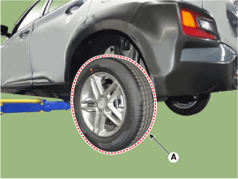
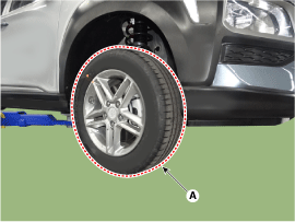
| 10. |
Loosen the rear wheel nuts and then remove the wheel and tire (A) from
the rear hub.
|
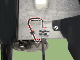
| 11. |
Remove the flare nut (A) and then rear brake hose.
|
| 12. |
Remove the fuel tank.
(Refer to Engine Control Fuel System "Fuel Tank")
|
| 13. |
Remove the fuel and brake line protector (A).
|
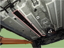
| 14. |
Separate the fixing clip (A) from the brake line using a driver.
|
| 15. |
Remove the brake line from the bottom of the vehicle to prevent damage.
|
| 1. |
Turn ignition switch OFF and disconnect the negative (-) battery cable.
|
| 2. |
Disconnect the brake fluid level switch connector (A).
|
| 3. |
Remove the brake fluid from the reservoir tank with a syringe after
remove the reservoir cap.
|
| 4. |
Remove the front wheel and tire (A) from front hub.
[Front]
[Rear]
|
| 5. |
Remove the brake hose cilp (A).
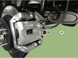
|
| 6. |
Separate the brake tube after loosening the brake tube flare nut (B).
[Front]
[Rear]
|
| 7. |
Remove the brake hose bracket bolt (A).
|
| 8. |
Loosen the brake hose mounting bolt (A) from the caliper and then remove
the brake hose.
[Front]
[Rear]
|
| Inspection |
| 1. |
Check the brake tubes for cracks, crimps and corrosion.
|
| 2. |
Check the brake tube flare nuts for damage and fluid leakage.
|
| Installation |
| 1. |
To install, reverse the removal procedure.
|
| 2. |
After installing, bleed the brake system.
(Refer to Brake System - "Brake System Bleeding")
(Refer to Brake System - "ABS System Bleeding")
(Refer to Brake System - "ESP System Bleeding")
|
 Brake Line Components and components location
Components
...
 Brake Pedal Components and components location
Components
1. Stop lamp switch
2. Brake pedal arm assembly
3. Brake member assembly
4. Return spring
...
Other information:
Hyundai Kona (OS) 2018-2026 Service Manual: Schematic diagrams
Schematic Diagrams
[MDPS]
Terminal function
Type
Pin No
Description
Battery
1
Battery +
2
Battery -
Vehicle speed
1
...
Hyundai Kona (OS) 2018-2026 Service Manual: Direct Electro Hydraulic Actuator Coupling Repair procedures
Inspection
•
All units are filled up with coupling fluid (ultra-low viscosity
ATF) prior to shipping. Inspection, fill-up, and replacement
of coupling fluid is therefore n ...
