Hyundai Kona: Parking Distance Warning-Foward/Revers / Description and operation
Hyundai Kona (OS) 2018-2026 Service Manual / Body Electrical System / Parking Distance Warning-Foward/Revers / Description and operation
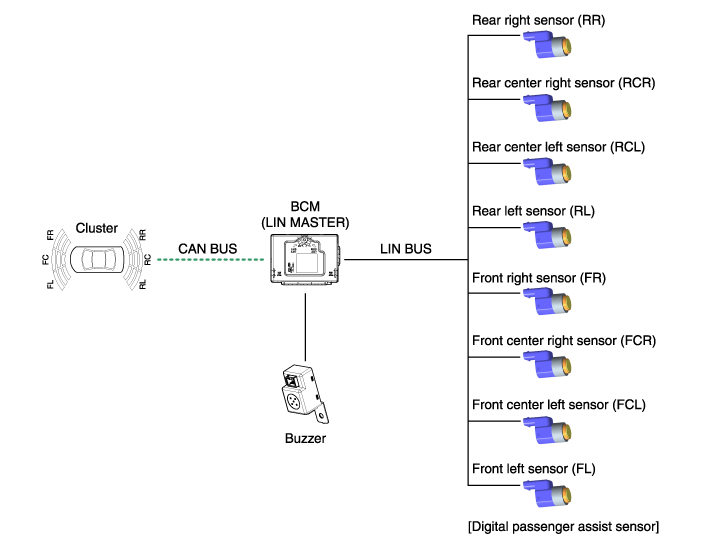
| System Overview |
PDW-R (Parking Distance Warning- Revers) is an electronic driving aid that
warns the driver to be cautious while parking or driving at low speed. The
sensor uses ultrasonic waves to detect objects within proximity of the vehicle.
PDW-R consists of four PDW-F sensors which are detecting the obstacles and
transmit the result separated into three warning levels, the first, second
and third to BCM by Lin communication. BCM decides the alarm level by the
transmitted communication message from the slave sensors, and then operates
the buzzer or transmits the data for display.
System Operation Specification
| 1. |
INIT mode
|
| 2. |
NORMAL Mode
|
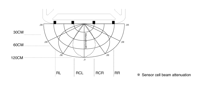
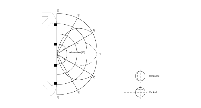
Sensing Area
| 1. |
Measurement condition ŌĆō PVC pole (diameter 75mm, length 1m), normal
temperature
|
| 2. |
Distance range detected objects (Measured directly in front of sensor)
61cm(24.0in) - 120cm(47.2in) : ┬▒ 15cm(5.9in)
31cm(12.2in) - 60cm(23.6in): ┬▒ 15cm(5.9in)
Less than 30cm(11.8in) : ┬▒ 10cm(3.9in)
|
Horizontal Sensing Area
Vertical Sensing Area
Distance Measurement
| Direct Measurement |
Transmission and Reception are executed with one sensor
(RL, RCL, RCR, RR each sensor execution)
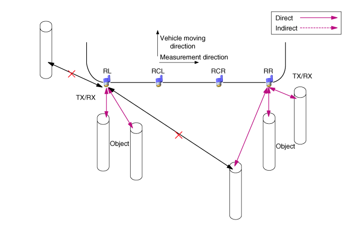
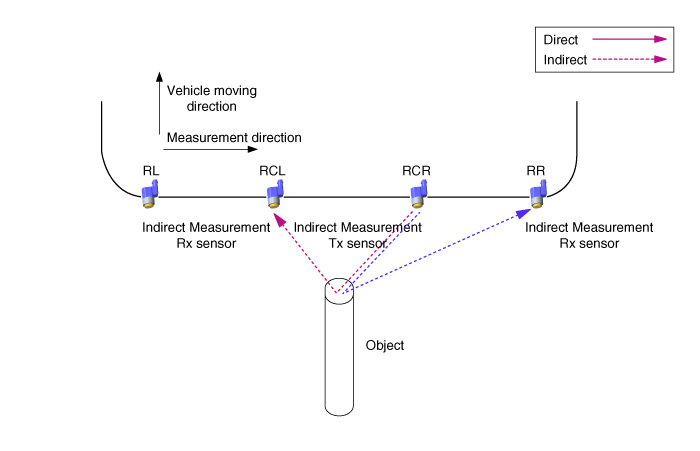
| Indirect Measurement |
(RCL ŌåÆ RL, RCL ŌåÆ RCR, RCR ŌåÆ RCL, RCR ŌåÆ RR Execution in order)
With two or three sensors, one of them sends the transmission and the others
get the reception.
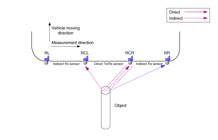
| Direct and Indirect Measurement at once |
With two or three sensors, the one sensor performs both transmission and
reception, and the others perform only reception.
PDW-R alarm system
When the PDW-R sensor detects the object, warning is operated by audible
alarm device as like buzzer. PDW-R sensor sends data to BCM via LIN communication
and BCM implements audible warning for each PDW-R SENSOR by priority. And
it performs a role of gateway only when it sends visible alarm device such
as Cluster.
| ŌĆō |
Sensor buzzer/display information processing method of BCM In case
of RL/RR sensor information, the BCM handles each sensor information
directly about Display and buzzer output function. Buzzer output
of CL/CR sensor, BCM handles center combination information by priority
both sensor.
|
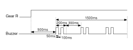
System Operation Spec
When the system has the power (after IGN ON and R gear), MICOM checks every
sensor channel. In case it finds any error, it gives off the buzzer for
300ms after 500ms.If an error is found even in a sensor, it gives off the
buzzer corresponding to the faulty sensor, instead of initial starting alarm.
The operation to enter the normal mode is as follows.
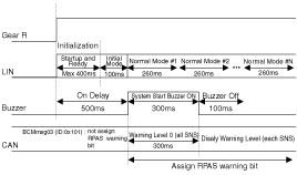
With the R gear put in the car, the system is operated as follows.
With the R gear released, the system is operated as follows.
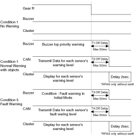
ŌĆ╗ The acceptable error range on waveform is ┬▒10%.
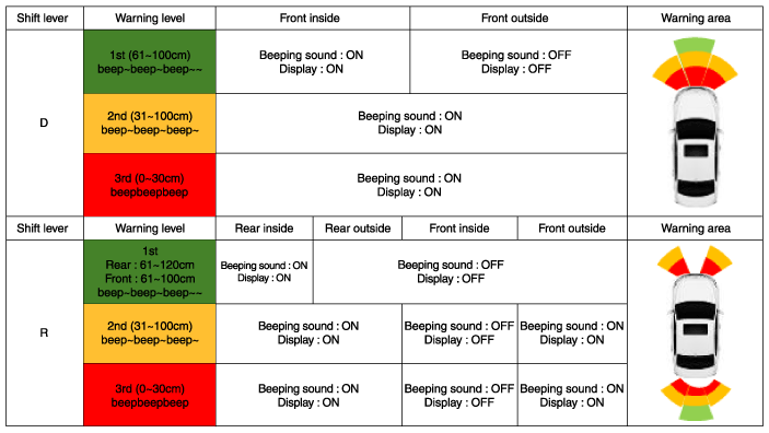
Alarm Output Specification Classified by Distance Between Sensors
Condition logic according to priority of alarm level is as below. (the identical
sensor)
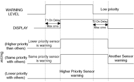
*╬▒ value definition
| 1. |
low priority sensor off : ╬▒ = 0ms
|
| 2. |
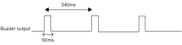
low priority sensor is 1st warning level : ╬▒ < 340ms
|
| 3. |
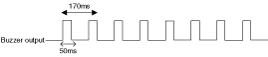
low priority sensor is 2nd warning level : ╬▒ < 170ms
|
*╬▓ value definition
| 4. |
low priority sensor is 1st warning level : ╬▓ = 1700ms
|
| 5. |
low priority sensor is 2nd warning level : ╬▓ = 1700ms
|
| 6. |
low priority sensor is 3rd warning level : ╬▓ = 700ms
|
Alarm control by sensing distance is as follows.
| 7. |
First warning area (61cm-120cm)
|
| 8. |
Second warning area (31cm-80cm)
|
| 9. |
Third warning area (less than 30cm)
|

| 10. |
Alarm fo ultrasonic sensor
If one or more front/rear paking assistance sensor have any fault,
alarm will sound and warning message will be displayed (cluster).
|
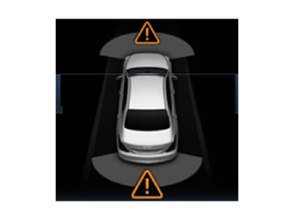

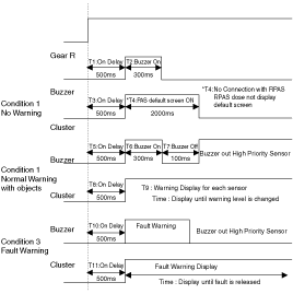
Visible Alarm Indicator Specification
When the gear shifts to R, the cluster controls the indicator as the following
picture.
When the system detects an object, it immediately turns on the indicator.
If an object disappears while the PDW-R detecting operation, the indicator
remains on for 2 sec. before being turned off.
(But when it turns third step alarm to No alarm status, it lights third
step alarm for two second and turns out.)
| ŌĆō |
It shows only the detecting position of obstacles.
|
| ŌĆō |
In third level alarm, indicator flickers at intervals of a second.
|
| ŌĆō |
In normal alarm mode, integrated display of RCR/RCL
|
Communication Standard
This section defines the communication between PDW-R and BCM.
PDW-R send a detecting result of object and sensor diagnosis result to BCM
according to this document, and BCM takes a role to issue an alarm.
Indicator shows the transmitted position and alarm data, in the alarm mode,
it finds the nearest DATA and alarms the nearest DATA first.
(Ex. In case, RL isthe first-step alarm and RR is the third step, RR alarm
has priority.)
 Components and components location
Component Location
1. BCM (Body Control Module)
2. Ultrasonic sensor
...

Other information:
Hyundai Kona (OS) 2018-2026 Service Manual: Roof Rack Components and components location
Components Location
1. Roof rack assembly
...
Hyundai Kona (OS) 2018-2026 Service Manual: Fender Garnish Repair procedures
Replacement
ŌĆó
Put on gloves to prevent hand injuries.
ŌĆó
Wh ...
┬® 2018-2026 www.hkona.com
