Hyundai Kona: Intake and Exhaust System / Exhaust Manifold Repair procedures
| Removal and Installation |
| 1. |
Disconnect the battery negative terminal.
|
| 2. |
Remove the engine cover.
(Refer to Engine and Transaxle Assembly - "Engine Cover")
|
| 3. |
Remove the engine room under cover.
(Refer to Engine and Transaxle Assembly - "Engine Room Under Cover")
|
| 4. |
Loosen the drain plug and drain the coolant and remove the radiator
cap to speed draining.
(Refer to Cooling System - "Coolant")
|
| 5. |
Remove the air duct and air cleaner assembly.
(Refer to Intake and Exhaust System - "Air Cleaner")
|
| 6. |
Remove the battery.
(Refer to Engine Electrical System - "Battery")
|
| 7. |
Remove the engine control module (ECM).
(Refer to Engine Control/Fuel System - "Engine Control Module (ECM)")
|
| 8. |
Remove the front muffler.
(Refer to Intake and Exhaust System - "Muffler")
|
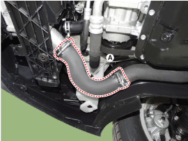
| 9. |
Remove the intercooler inlet hose and pipe.
|

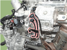
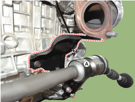
| 10. |
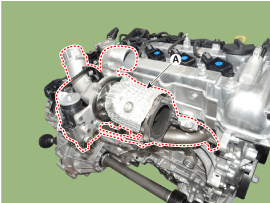
Remove the WGT control actuator (EWGA) connector (A).
|
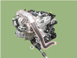
| 11. |
Remove the turbo charger water hose (A).
|
| 12. |
Remove the turbo charger water pipes (A).
|
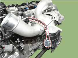
| 13. |
Remove the front oxygen sensor connector (A) .
|
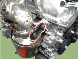
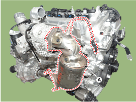
| 14. |
Remove the warm-up catalytic converter (WCC) stay A (A).
|
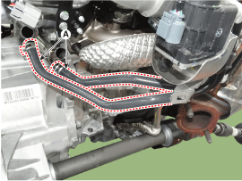
| 15. |
Remove the turbo charger oil drain pipe (A).
|
| 16. |
Remove the warm-up catalytic converter (WCC) stay B (A).
|
| 17. |
Remove the Warm-up catalytic converter (WCC) (A).
|
| 18. |
Remove the turbo charger oil feed pipe (A).
|
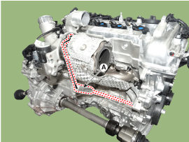
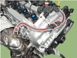
| 19. |
Remove the turbo charger module heat protector (A).
|
| 20. |
Remove the engine mounting support bracket .
(Refer to Engine and Transaxle Assembly - "Engine Mounting")
|
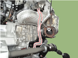
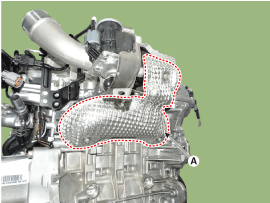
| 21. |
Remove the turbo charger module (A).
|
| 22. |
Remove the turbo manifold module gasket (A).
|
| 23. |
Install in the reverse order of removal.
|
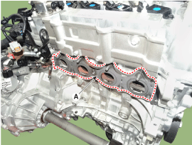
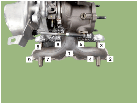
 Exhaust Manifold Components and components location
Components
1. Turbo manifold gasket
2. Turbo manifold module
3. Warm-up catalytic converter (WCC)
4. Warm-up catalytic converter (WCC) gasket
5. Oil feed p ...
 Intercooler Components and components location
Components
1. Intercooler
2. Intercooler air guard
3. Intercooler inlet hose
4. Intercooler inlet pipe
5. Intercooler outlet hose
6. Intercooler outlet ...
Other information:
Hyundai Kona (OS) 2018-2026 Service Manual: Description and operating principle
Description and Operation
Wireless Power Charger System
During ACC or IG ON, battery voltage is supplied to the wireless power charger
system to transmit an output of 5 W to mobile phone.
Mobile phones certified with the wireless charging standard WPC (Qi 1.1.2 ...
Hyundai Kona (OS) 2018-2026 Service Manual: Injector Repair procedures
Inspection
1.
Turn the ignition switch OFF.
2.
Disconnect the injector connector.
3.
Measure resistance between the injector terminals 1 and 2.
4.
Check that the resistance is withi ...
